Project_4_ESP32_PIR_Motion_Sensor.ino, then open it in the Arduino IDE (setup: Foundation 3).
diagram.json above and paste its wiring in to load the circuit.
🎯 Objective
By the end of this project, you will:
- Understand how a PIR sensor detects movement, and what it cannot detect.
- Wire a 5 V sensor to the ESP32 safely and know why it uses
VINrather than3V3. - Use
millis()to build a non-blocking timer and explain whydelay()is the wrong tool for it. - Track state across loop iterations with a flag, so an event fires once instead of continuously.
- Build a small alarm that holds its output for a few seconds after the last movement.
1How the PIR sensor works
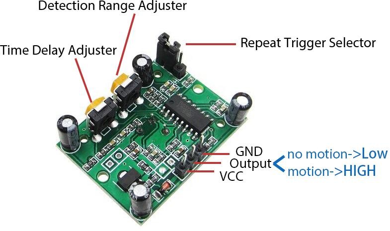
- A PIR senses the infra‑red heat of living bodies and triggers on change, a warm, moving object.
- OUT = HIGH on motion, LOW otherwise.
- A person standing perfectly still may not be detected; a moving heat‑less object (robot, car) isn't either.
The physics: pyroelectric crystal + Fresnel lens
Under the white dome sits a pyroelectric sensor element (commonly an LHI778 on HC‑SR501 boards), split into two halves. A pyroelectric crystal generates a tiny voltage whenever the infra‑red hitting it changes: a body at skin temperature radiates strongly around 9–10 µm, the band this crystal is tuned to. A perfectly static heat source produces a constant voltage the circuit ignores; only a change produces a usable signal, which is why the sensor is called "passive": it never emits anything itself, it only listens.
The crystal alone has almost no directionality, so the dome is not just a cover, it is a multi‑faceted Fresnel lens that splits the sensor's field of view into several narrow zones. As a warm body crosses from one zone into the next, the two halves of the element see different amounts of IR and briefly disagree, and that differential pulse is what the sensor is actually built to catch. That is also why the sensor picks up motion across its field of view far more reliably than motion straight toward or away from it.
A second chip on the board, the BISS0001 PIR motion detector IC, amplifies that microvolt‑level signal, filters noise, compares it against a threshold, and drives the digital OUT pin. The same chip implements the two trimmers and the jumper described next.
Configuration: two trimmers and a jumper
The two orange trimmers adjust sensitivity/range and time delay. The jumper (usually labeled H and L) selects retrigger mode:
- Sensitivity (distance) trimmer: sets the detection range, roughly 3–7 m, over a detection cone of about 100–120° depending on the board revision. Turn it down if the sensor triggers on motion outside the area you actually care about.
- Time delay trimmer: sets how long
OUTstays HIGH after the last motion, adjustable from about 3 s up to roughly 5 minutes. If your board'sOUTstays HIGH far longer than this project's 3‑secondholdTime, turn this trimmer fully toward its minimum so the sensor's own hold time isn't what you end up timing. - H (repeatable trigger, the default): each new motion during the sensor's own delay window resets that window, so its output stays HIGH as long as something keeps moving.
- L (single trigger): the output goes HIGH once, holds for the delay set by the time‑delay trimmer, then drops LOW and ignores further motion for about 2.5 s, even if something is still moving.
Defaults (H, trimmers centered) are fine for this project. If the buzzer holds on far longer than the sketch's own 3‑second holdTime, someone is still moving in front of the sensor and H mode keeps resetting the sensor's output: that's expected, not a bug (see Troubleshooting).
Datasheets (included in this project folder, download for the full pinout, dimensions, and functional description):
2Non‑blocking timing: delay() vs millis()
delay(3000) freezes the whole program for 3 s. Instead we record when motion last happened and check elapsed time: keeping the loop responsive:
lastMotionTime = millis();                    // remember "now"
if (millis() - lastMotionTime >= holdTime) {  // has enough time passed?
  ...
}
This pattern scales to programs doing many things at once, a habit worth building early.
3Parts Required
| Qty | Part | Notes |
|---|---|---|
| 1 | ESP32 · breadboard · jumper wires | - |
| 1 | HC‑SR501 PIR | Powered from 5 V |
| 1 | Active buzzer | Beeps on its own when powered |
4Wiring the Circuit
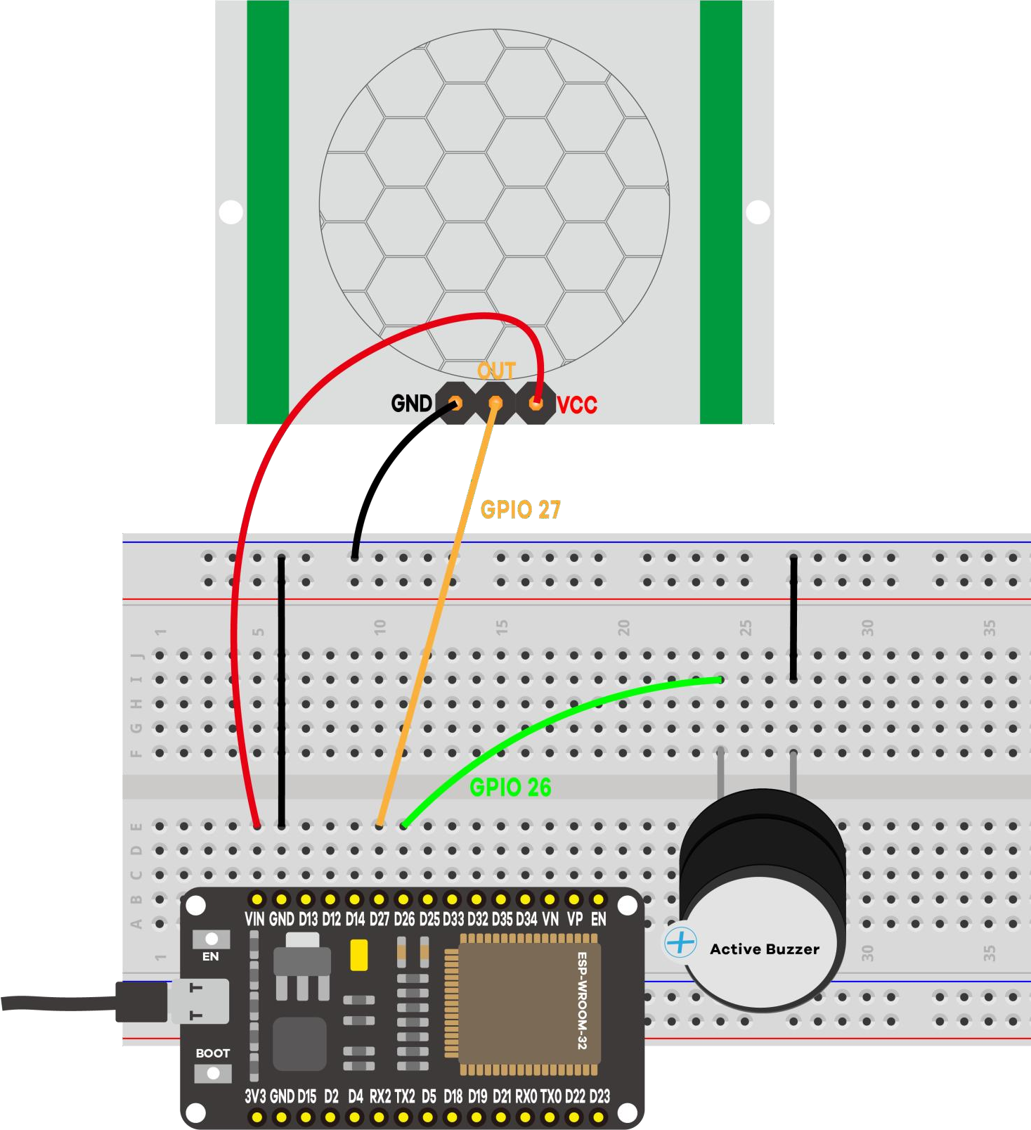
| From | To |
|---|---|
| PIR VCC | VIN (5 V) |
| PIR GND | GND |
| PIR OUT | GPIO 27 |
| Buzzer + | GPIO 26 |
| Buzzer − | GND |
VIN when USB‑powered). Its OUT signal is still ESP32‑safe.+ (sometimes marked S) and −. Wire it backwards and it stays silent rather than damaging anything, since the module's own driver blocks reverse current, but it will not beep until you flip it (see Troubleshooting).5Code Walkthrough: Understanding the Sketch
Let's walk through the sketch so you understand what each line does and why.
Step 1: Pins, the hold time, and the state we remember
const int buzzerPin    = 26;  // active buzzer -> GPIO 26
const int motionSensor = 27;  // PIR OUT       -> GPIO 27

const long holdTime = 3000;         // hold the buzzer this long (ms)
unsigned long lastMotionTime = 0;  // when motion was last seen
bool alarmActive = false;           // is the buzzer sounding right now?
Two variables carry the logic. lastMotionTime is a timestamp, not a countdown: it stores the moment motion was last seen. alarmActive is a flag recording what the program already did, which stops the buzzer being switched on again on every pass through loop().
unsigned long matters: millis() passes the range of a normal int in about 32 seconds, but an unsigned long holds roughly 49 days.Step 2: one-time preparation in setup()
pinMode(buzzerPin, OUTPUT);      // the buzzer is driven by the ESP32
pinMode(motionSensor, INPUT);    // the PIR drives this pin
digitalWrite(buzzerPin, LOW);    // start silent
Note the explicit digitalWrite(buzzerPin, LOW). A freshly configured output pin is not guaranteed to be in the state you want, and starting an alarm project with an unexpected beep is a poor demo.
Step 3: loop() watches for motion and times the hold
void loop() {
  bool motion = (digitalRead(motionSensor) == HIGH);

  if (motion) {
    lastMotionTime = millis();          // remember when we last saw motion
    if (!alarmActive) {                 // only act on the RISING edge
      digitalWrite(buzzerPin, HIGH);
      alarmActive = true;
      Serial.println("[EVENT] MOTION detected  -> buzzer ON");
    }
  } else {
    // No motion now: stop once the hold time has elapsed.
    if (alarmActive && (millis() - lastMotionTime >= holdTime)) {
      digitalWrite(buzzerPin, LOW);
      alarmActive = false;
      Serial.println("[EVENT] No motion (hold elapsed) -> buzzer OFF");
    }
  }
}
Read it as two questions asked thousands of times per second: is there motion right now? and, if not, has it been quiet long enough to stop? Because the loop never blocks, the sensor is still read while the hold counts down, so fresh motion pushes lastMotionTime forward and extends the alarm.
Key concepts: what each line really does
| Code | What it does |
|---|---|
digitalRead(motionSensor) == HIGH | The HC-SR501 drives OUT high while it sees movement, so reading it is exactly like reading a button. |
millis() | Milliseconds since boot. It keeps counting no matter what your code is doing, which is what makes it usable as a clock. |
lastMotionTime = millis() | Stores "now" as a timestamp. Every fresh detection overwrites it, restarting the hold period. |
millis() - lastMotionTime >= holdTime | The non-blocking timer: subtract the stored moment from the current one to get elapsed time, then compare. No waiting involved. |
if (!alarmActive) | Edge detection in flag form. Without it the buzzer would be re-commanded ON and the message re-printed on every pass. |
bool alarmActive | The program's memory of its own output state, so it can tell "start the alarm" from "the alarm is already running". |
Expected output on the Serial Monitor
==============================================
 Project 4: ESP32 PIR Motion Sensor + Buzzer
==============================================
PIR OUT -> GPIO 27
Buzzer  -> GPIO 26
Buzzer holds ON for 3000 ms after motion stops.
NOTE: the PIR needs ~30-60 s to warm up after power-on.
----------------------------------------------
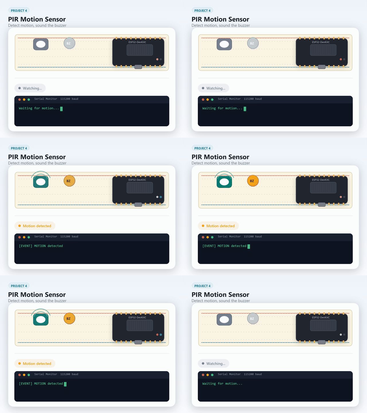
[EVENT] MOTION detected  -> buzzer ON
[EVENT] No motion (hold elapsed) -> buzzer OFF
Going further: swap in the obstacle-avoidance module
The kit's obstacle‑avoidance module reads exactly like the PIR: a digital pin that goes HIGH or LOW depending on what its sensor sees, this time IR reflectance instead of body heat.
| Obstacle module pin | ESP32 |
|---|---|
| VCC | 3.3 V |
| GND | GND |
| OUT | GPIO 27 (same pin as the PIR) |
3V3 instead keeps the logic level safe, and the sensor still works fine at that voltage, just with slightly shorter range.The trimmer on the module sets detection distance: turn it to tune how close an object has to get before OUT goes HIGH. digitalRead(motionSensor) in the sketch above doesn't change at all: an obstacle module and a PIR are both "is something there right now" sensors, just tuned to different physics.
This is the sensor half of Project 13's Obstacle alarm idea.
[EVENT] MOTION detected lines print while you stay still? Try it and count.6Demonstration
🎯 Knowledge Check
1. What does a PIR sensor detect?
2. Why should you use millis() instead of delay() to keep the alarm running?
3. What data type should you use for millis() variables?
4. The HC-SR501 PIR sensor needs 5 V power. Is its output signal safe for an ESP32 GPIO?
5. What does the "state flag" pattern (alarmActive) prevent?
8Wrapping Up: What You've Learned
You now have a sensor driving an actuator, with timing that does not freeze the program. The key takeaways:
- A PIR sensor reports change in infra-red heat, so it sees a moving warm body but not a still one, and not a cold moving object. It also needs 30 to 60 s to warm up.
- Some modules need 5 V.
VINsupplies it while the board is USB-powered, and the HC-SR501's 3.3 V output is safe to feed back into a GPIO. millis()gives you a clock that never stops. Storing a timestamp and subtracting it later is the standard non-blocking timer pattern.delay()would have worked here but blocks everything. Once a project has two things to do at once (Projects 8 and 11 do), blocking code stops being an option.- A state flag like
alarmActivelets the program tell a new event from an ongoing condition, which keeps the log clean and the output stable.
Now try
- Countdown timer: Instead of a fixed hold time, display a countdown on the Serial Monitor ("Alarm active, 3s remaining... 2s... 1s...").
- Obstacle-avoidance swap: Replace the PIR with the kit's obstacle-avoidance module. It reads the same way (digital HIGH/LOW) but must be powered from 3.3 V, not 5 V.
9Troubleshooting
| Symptom | Likely cause | Fix |
|---|---|---|
| Always triggers | Warming up / sensitivity too high | Wait 60 s; lower the sensitivity trimmer |
| Never triggers | PIR on 3.3 V, or OUT mis‑wired | Power VCC from VIN (5 V); OUT → GPIO 27 |
| Buzzer silent | Reversed / wrong pin | + → GPIO 26, − → GND |
| Buzzer never stops | Constant motion / retrigger jumper | Hold still; check the jumper |
| Monitor blank | Wrong baud | Set it to 115200 |