Project_3_ESP32_PWM.ino, then open it in the Arduino IDE (setup: Foundation 3).
diagram.json above and paste its wiring in to load the circuit.
🎯 Objective
By the end of this project, you will:
- Understand the concept of Pulse Width Modulation (PWM) and duty cycle.
- Learn how the ESP32's built-in LED PWM controller works (16 channels, configurable frequency & resolution).
- Generate analog‑looking output from a digital pin to smoothly fade an LED.
- Use the
ledcAttach()andledcWrite()functions (ESP32 Core v3.x+ API). - Observe the difference between a digital (ON/OFF) and an analog‑style (dimming) output.
In short: we'll build a simple circuit that dims an LED using the LED PWM controller of the ESP32.
1What is PWM?
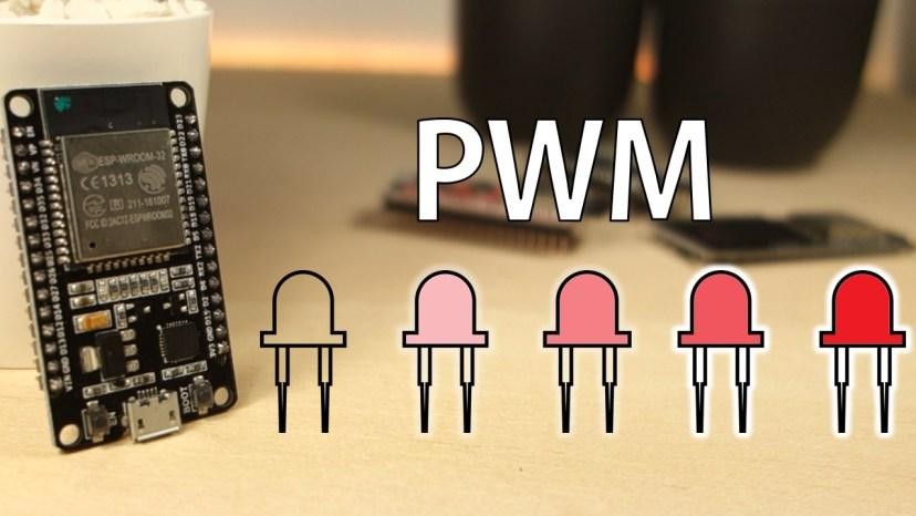
A digital pin is only ever fully ON (3.3 V) or OFF (0 V). But switch it on/off very fast and the LED's average brightness follows the fraction of time it's ON: the duty cycle:
The switching here is 5000 Hz (far faster than the eye), so you see steady brightness, not flicker. That's Pulse Width Modulation.
2The ESP32 LED PWM Controller
The ESP32 has a dedicated LED PWM controller that can generate PWM signals with different properties. With the ESP32 Core v3.x+ Arduino IDE, using it is simple: just two functions.
Step-by-step configuration
| Step | What you do | Our choice |
|---|---|---|
| 1. Choose a GPIO pin | Any output‑capable pin can be used as a PWM pin. | GPIO 4 |
| 2. Set the signal frequency | How many times per second the pin switches ON/OFF. Higher = smoother. | freq = 5000 (5 kHz) |
| 3. Set the duty cycle resolution | Number of bits for the duty value. 8‑bit → 0…255, 10‑bit → 0…1023, up to 16‑bit. | resolution = 8 (0–255) |
| 4. Attach PWM to the pin | Tell the ESP32 to enable PWM on that GPIO with your frequency & resolution. | ledcAttach(ledPin, freq, resolution) |
| 5. Write the duty cycle | Set the brightness value (0 = off, 255 = full on). | ledcWrite(ledPin, dutyCycle) |
The two functions that do all the work: no channel management needed:
ledcAttach(pin, freq, resolution);      // 1-4: enable PWM on a GPIO
ledcWrite(pin, dutyCycle);              // 5: set brightness (0..255)
ledcSetup + ledcAttachPin), the v3.x+ ledcAttach() combines both steps and ledcWrite() now takes the GPIO pin, not a channel. This is much simpler!3Parts Required
| Qty | Part | Notes |
|---|---|---|
| 1 | ESP32 · breadboard · jumper wires | - |
| 1 | LED | Has polarity: long leg = anode (+) |
| 1 | 220 Ω resistor | Limits current to protect the LED |
4Wiring the Circuit
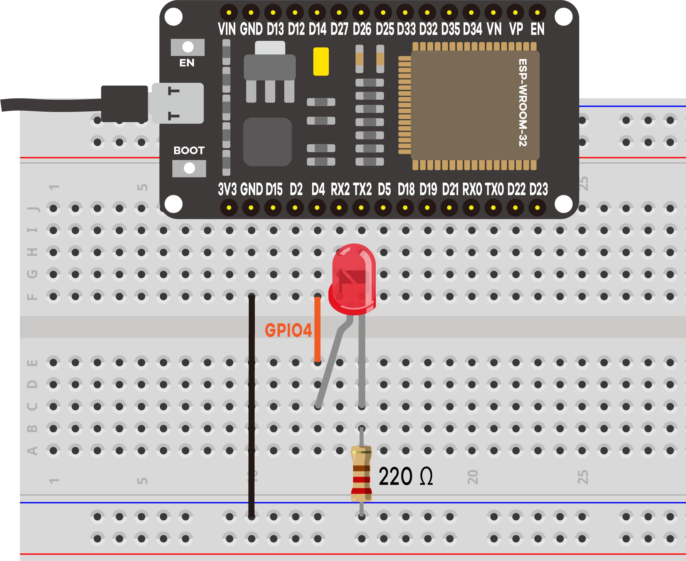
- GPIO 4 → 220 Ω → LED anode (long leg)
- LED cathode (short leg) → GND
That's it: just three connections. (Any output‑capable pin works; the sketch uses GPIO 4.)
5Code Walkthrough: Understanding the Sketch
Let's walk through the key parts of the sketch so you understand what each line does and why. The code is only about 35 lines but packs in several important concepts.
Step 1: Pin definition & PWM configuration constants
// LED (through 220 ohm) -> GPIO 4
const int ledPin = 4;

// PWM configuration
const int freq = 5000;        // 5 kHz: fast enough to avoid flicker
const int resolution = 8;    // 8‑bit → duty cycle value 0..255
ledPin identifies which GPIO the LED is on. Then we define two PWM properties: the frequency (how many times per second the pin switches on/off) and the resolution (how many distinct brightness levels: 8 bits = 256 levels, from 0 to 255). The ESP32 Core v3.x+ API manages the internal PWM channel for you, so you don't need to pick one.
Step 2: configuring the PWM hardware in setup()
void setup() {
  Serial.begin(115200);
  delay(500);                   // give the Serial Monitor a moment to connect

  // Configure PWM on the GPIO pin (ESP32 Core v3.x+ API)
  ledcAttach(ledPin, freq, resolution);

  ...                            // then print the banner
}
A single function call prepares the PWM hardware:
ledcAttach()tells the ESP32: "enable PWM on GPIO 4 at 5000 Hz with 8‑bit resolution". This internally allocates a PWM channel, configures the timer, and routes the signal to the pin, all in one step.
In older ESP32 Core versions you needed two separate calls (ledcSetup + ledcAttachPin), but v3.x+ simplifies it down to one.
Step 3: fading up, then down, forever in loop()
void loop() {
  // Fade in: duty cycle 0 -> 255 (0% -> 100% brightness)
  Serial.println("Fading UP   (0 -> 255)");
  for (int dutyCycle = 0; dutyCycle <= 255; dutyCycle++) {
    ledcWrite(ledPin, dutyCycle);
    delay(15);
  }

  // Fade out: duty cycle 255 -> 0 (100% -> 0% brightness)
  Serial.println("Fading DOWN (255 -> 0)");
  for (int dutyCycle = 255; dutyCycle >= 0; dutyCycle--) {
    ledcWrite(ledPin, dutyCycle);
    delay(15);
  }
}
Key concepts: what each part really does
| Code | What it does |
|---|---|
ledcAttach(pin, freq, resolution) | Enables PWM on the specified GPIO pin. Internally this allocates a PWM channel, sets up the hardware timer with your frequency & resolution, and connects the pin, all in one call. |
ledcWrite(pin, dutyCycle) | Sets the duty cycle (0 = always OFF, 255 = always ON). The hardware handles the fast switching: your code just says how bright. Note: in v3.x+ the first argument is the GPIO pin, not a channel. |
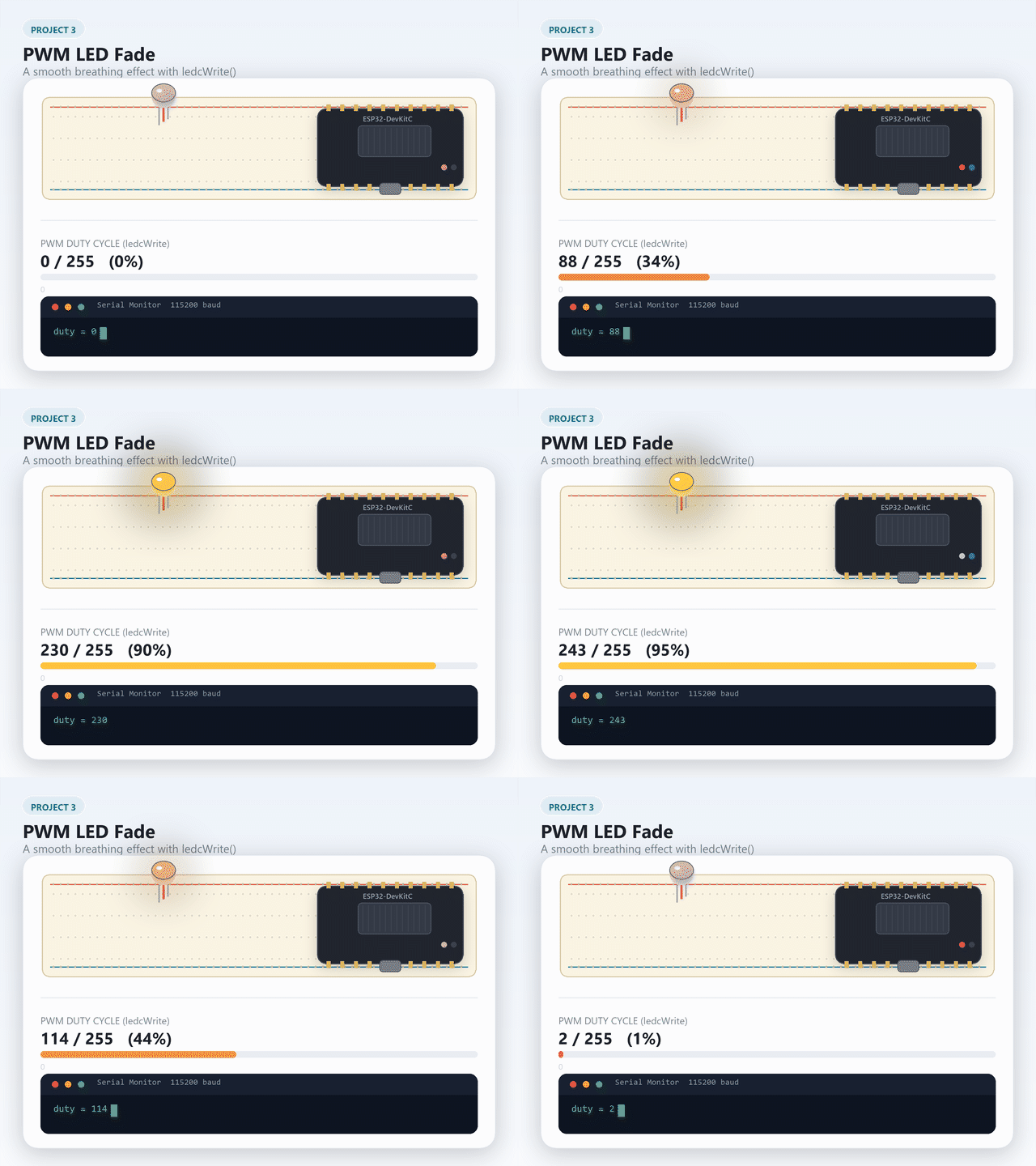
for (int d = 0; d <= 255; d++) | A loop that counts from 0 to 255. Each iteration increases brightness by one step. With delay(15), the full fade takes 256 × 15 ms ≈ 3.8 seconds. |
delay(15) | Pauses 15 ms between each step. Without it the LED would jump from off to full brightness in microseconds: no visible fade. |
Going further: frequency vs. resolution, and why they trade off
ledcAttach() takes both a frequency and a resolution, and the two aren't independent: the ESP32's PWM hardware (LEDC) derives both from one internal clock (up to 80 MHz), so the resolution you can ask for is capped by:
max resolution (bits) = floor( log2( 80,000,000 / frequency ) )
At this project's 5 kHz, that ceiling is about 13 bits (8192 levels), so the 8‑bit (256‑level) resolution used here has plenty of headroom. Double the frequency to 10 kHz and the ceiling drops to about 12 bits: the higher the frequency, the fewer resolution steps fit in each PWM cycle. Ask for more resolution than the frequency allows and ledcAttach() simply can't deliver it.
For a fading LED this rarely matters: your eye can't tell 256 brightness levels from 8192. It starts to matter once a project uses PWM to make a pitch instead of a brightness, since each musical note is its own frequency, and each one comes with its own resolution ceiling.
Going further: melodies on the passive buzzer
Swap the LED for the kit's passive buzzer and the same PWM idea makes sound instead of light: a buzzer just needs the right frequency, not a specific duty cycle.
| Passive buzzer pin | ESP32 |
|---|---|
| + | GPIO 4 (same pin as the LED, no resistor needed) |
| − | GND |
const int buzzerPin = 4;

void setup() {
  ledcAttach(buzzerPin, 1000, 8);   // any starting frequency; loop() changes it
}

void loop() {
  ledcWriteTone(buzzerPin, 262);   // C4
  delay(300);
  ledcWriteTone(buzzerPin, 294);   // D4
  delay(300);
  ledcWriteTone(buzzerPin, 330);   // E4
  delay(300);
  ledcWriteTone(buzzerPin, 0);     // silence
  delay(1000);
}
ledcWriteTone(pin, frequency) is ledcWrite()'s sibling for exactly this job: it picks a 50% duty cycle at whatever frequency you ask for, so the pin still needs ledcAttach() first, but you stop thinking about duty cycle entirely and just name notes (262 Hz is a middle C). Writing 0 silences it. Compare this with the kit's active buzzer, used nowhere in this course: it only knows one pitch, baked into its own tiny driver chip, and beeps at that pitch the instant it gets any signal at all. A passive buzzer has no such chip, which is exactly what lets you pick the frequency yourself.
digitalWrite(pin, HIGH). That's only true for an active buzzer. Try it on a passive one and you'll get silence, or a faint click, because there's no PWM signal telling it what pitch to make. "Buzzer" is not one part with one behavior: check which kind you're holding before you wire it.This is the buzzer half of Project 13's Obstacle alarm and Light‑and‑sound alert ideas.
Expected output on the Serial Monitor
==============================================
 Project 3: ESP32 PWM (Analog Output)
==============================================
LED (PWM) -> GPIO 4
PWM: 5000 Hz, 8-bit (duty 0..255)
The LED should fade up and down continuously.
----------------------------------------------
Fading UP   (0 -> 255)
Fading DOWN (255 -> 0)
Fading UP   (0 -> 255)
...
The sketch prints one line per direction change: printing all 256 steps would flood the monitor. Watch the LED, not the text!
delay(15) and 256 steps? Do the math, then upload and time it.6Demonstration
🎯 Knowledge Check
1. What does PWM stand for?
2. At 8-bit resolution, what range of values can you write with ledcWrite()?
3. What is the correct Core v3.x+ function to set up PWM on a pin?
4. What does a 50% duty cycle look like to the human eye on an LED?
5. Why can't you use digitalWrite() to produce sound on a passive buzzer?
8Wrapping Up: What You've Learned
In this project you've learned how to generate PWM signals with the ESP32 using the Arduino IDE. Here's a summary of the key takeaways:
- The ESP32 has a LED PWM controller that can generate PWM signals with different properties (16 internal channels, but the v3.x+ API manages them for you).
- To dim an LED, you follow 5 steps: (1) choose a GPIO pin, (2) set the frequency, (3) set the resolution, (4) attach PWM with
ledcAttach(), and (5) write the duty cycle withledcWrite(). - You can use any pin that can act as an output as a PWM pin: all output-capable pins work.
- With the ESP32 Core v3.x+ API,
ledcAttach()replaces the olderledcSetup()+ledcAttachPin()two-step process, andledcWrite()takes the GPIO pin (not a channel) as its first argument. - PWM at very low frequencies may cause visible flicker: 5000 Hz is a safe choice for LEDs.
Now try
- Potentiometer-controlled brightness: Read a potentiometer with
analogRead()(Project 2) and use its value as the PWM duty cycle instead of the automatic fade. - Play a melody: Use
ledcWriteTone()to play a sequence of musical notes on the passive buzzer. Look up the frequencies for notes C4 through B4 and play them in a simple tune.
9Troubleshooting
| Symptom | Likely cause | Fix |
|---|---|---|
| LED off | Reversed LED or mis‑wired pin | Long leg toward the 220 Ω / GPIO 4 side |
| Full‑on, no fade | Didn't upload / wrong pin | Re‑upload; confirm LED on GPIO 4 |
| Fades but flickers | Frequency too low | Keep freq at 5000 Hz |
| Monitor blank | Wrong baud | Set it to 115200 |