Project_10_ESP32_OLED_Display.ino, then open it in the Arduino IDE (setup: Foundation 3). Needs the Adafruit SSD1306 + GFX libraries.
diagram.json above and paste its wiring in to load the circuit.
🎯 Objective
By the end of this project, you will:
- Understand what I²C is: a two-wire bus that carries many devices, each with its own address.
- Drive a display through a pair of libraries, one for the chip and one for the graphics.
- Learn the buffer then push pattern every graphical display uses: draw into memory, then send the whole frame at once.
- Check that hardware actually started, and fail with a message that says what to fix.
- Use the SSD1306's built-in scrolling, which runs on the display chip rather than in your sketch.
1About the display & I²C
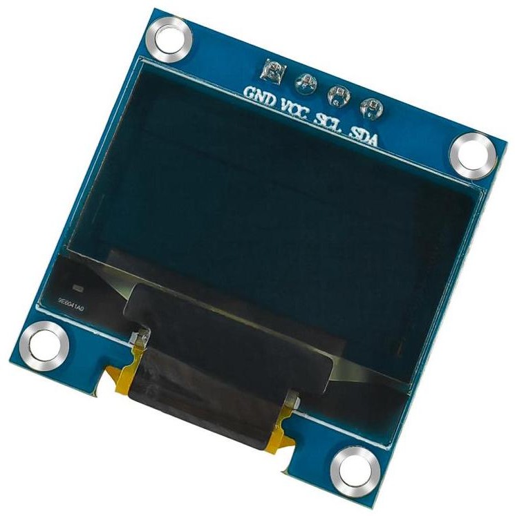
The SSD1306 is a crisp 128×64 monochrome OLED: self‑lit pixels, great contrast, low power. It talks over I²C, a two‑wire bus (SDA + SCL). ESP32 defaults: GPIO 21 (SDA), GPIO 22 (SCL). This module's I²C address is 0x3C.
Why GPIO 21 and GPIO 22 specifically? Nothing about I²C itself requires those two pins: most ESP32 GPIOs are multiplexed, routed through an internal GPIO matrix that can carry I²C, SPI, PWM, or UART signals on nearly any pin in software (Foundation 2 covers this multiplexing). 21 and 22 happen to match the Wire library's own defaults and the silkscreen labels every DevKit board has carried since Espressif's original reference design, which is why this sketch names them SDA_PIN and SCL_PIN and passes them to Wire.begin(SDA_PIN, SCL_PIN) explicitly rather than leaving pin selection to that hidden default. Changing one constant and rewiring accordingly is all it takes to move the bus to different pins.
| OLED pin | ESP32 |
|---|---|
| VCC | 3.3 V |
| GND | GND |
| SCL | GPIO 22 |
| SDA | GPIO 21 |
2Install the required libraries
Two Adafruit libraries (both in the Library Manager):
- Adafruit SSD1306 (driver)
- Adafruit GFX (graphics/text engine)
Restart the IDE after installing.
3Wiring the Circuit
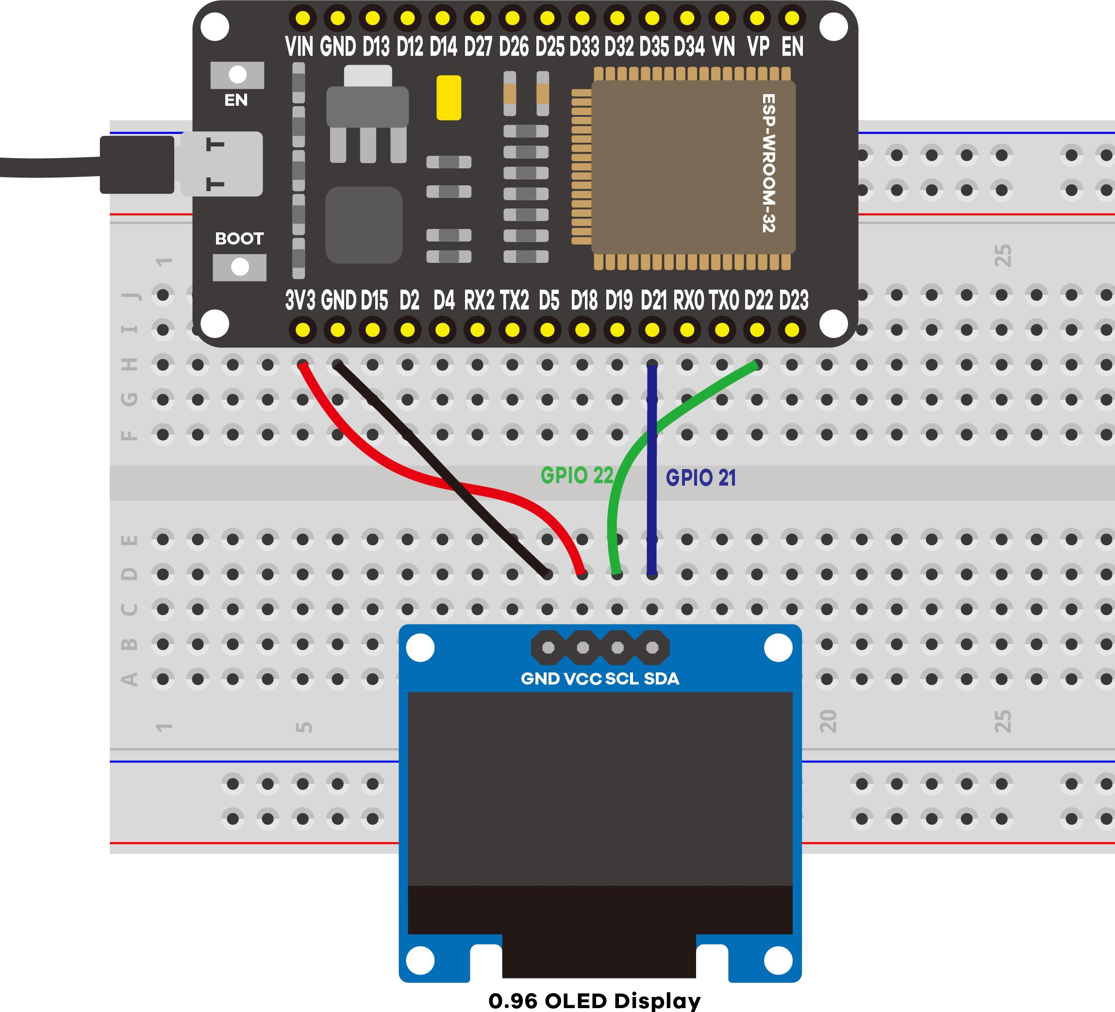
No resistors needed, because I²C lines are open-drain: a chip can only pull SDA or SCL low, never drive them high, so each line needs a resistor pulling it back up to 3.3 V between pulses. Breakout modules like this OLED carry those pull-up resistors on board already, which is standard for I²C parts, so the four wires above are the whole circuit.
4The drawing API
Clear → set style → position → print → push to the display. Nothing appears until display():
display.clearDisplay();          // erase the buffer
display.setTextSize(2);          // 1 = small ... bigger = larger
display.setTextColor(WHITE);     // white text on black
display.setCursor(0, 30);        // x, y start
display.println("LAFVIN");       // write into the buffer
display.display();               // <-- actually show it
Scrolling is built in: startscrollright(), startscrollleft(), stopscroll().
5Code Walkthrough: Understanding the Sketch
Short, but every line is worth understanding: this is the first project that talks to another chip rather than to a plain component.
Step 1: Two libraries and one display object
#include <Adafruit_GFX.h>
#include <Adafruit_SSD1306.h>
#include <Wire.h>

#define SCREEN_WIDTH  128   // OLED width, in pixels
#define SCREEN_HEIGHT 64    // OLED height, in pixels

#define SDA_PIN 21          // change to any free GPIO for I2C data
#define SCL_PIN 22          // change to any free GPIO for I2C clock

// I2C OLED, no reset pin (-1). Default I2C address 0x3C.
Adafruit_SSD1306 display(SCREEN_WIDTH, SCREEN_HEIGHT, &Wire, -1);
Three includes, three jobs. Wire.h is the ESP32's I²C driver: it knows how to wiggle SDA and SCL. Adafruit_SSD1306 knows the commands this particular chip understands. Adafruit_GFX is the generic drawing engine: shapes, fonts, cursor handling. That layering is why the println() you already know works on a screen.
SDA_PIN and SCL_PIN name the two I²C wires as constants instead of leaving bare numbers scattered through the sketch. Change either one line and rewire accordingly to move the bus: the banner print, the error message, and the Wire.begin() call in setup() all read from these two #defines.
The four arguments are width, height, which I²C bus to use (&Wire; the pins for that bus are assigned explicitly in setup(), not here), and a reset pin. This module has none, so that argument is -1.
Step 2: Open the I²C bus, then start the display
Wire.begin(SDA_PIN, SCL_PIN);

// Try to start the display at I2C address 0x3C
if(!display.begin(SSD1306_SWITCHCAPVCC, 0x3C)) {
  Serial.println("[OLED] ERROR: display not found!");
  Serial.printf("       Check SDA->%d, SCL->%d, VCC->3V3, GND->GND,\n", SDA_PIN, SCL_PIN);
  Serial.println("       and that the I2C address is 0x3C.");
  for(;;);   // stop here - nothing else to do without a display
}
Serial.println("[OLED] Display initialized OK.");
Wire.begin(SDA_PIN, SCL_PIN) is the line that actually configures the I²C bus on GPIO 21 and 22, and it has to run before display.begin(), which is why it comes first. Earlier versions of this sketch skipped this line and let the Adafruit_SSD1306 library call Wire.begin() with no arguments the first time display.begin() ran, quietly falling back to the ESP32 core's default pins. Calling it explicitly, with named constants, makes the pin choice something you read in the sketch instead of something you have to already know.
display.begin() returns false if nothing answers at address 0x3C, which is what a loose wire looks like from the sketch's point of view. Reporting it, with %d so the message always names the pins actually in use, is the whole difference between "my screen is broken" and "my SDA wire is in the wrong hole".
SSD1306_SWITCHCAPVCC tells the module to generate its own display voltage from the 3.3 V you supplied, using an internal charge pump. for(;;); is an intentional infinite loop: with no display there is nothing useful left to do.
Step 3: Draw into the buffer, then push it to the glass
display.clearDisplay();          // erase the buffer
display.setTextSize(2);          // 1 = small ... bigger numbers = larger
display.setTextColor(WHITE);     // white text on black
display.setCursor(0, 30);        // x, y start position
display.println("LAFVIN");       // write into the buffer
display.display();               // <-- actually show it on screen
The first five calls change nothing on the screen. The library keeps a 128×64 copy of the image in the ESP32's RAM and every drawing call edits that copy. Only display.display() sends it over I²C. Forgetting that last line is the most common OLED mistake, and it looks exactly like a dead screen.
Coordinates start at (0, 0) in the top-left corner, with y growing downward. At text size 2 each character is about 12×16 pixels, so a cursor at (0, 30) lands roughly in the middle of a 64-pixel-tall screen.
Step 4: loop() scrolls, and the display chip does the work
void loop() {
  display.startscrollright(0x00, 0x0F);
  delay(7000);
  display.stopscroll();
  delay(1000);
  display.startscrollleft(0x00, 0x0F);
  delay(7000);
  display.stopscroll();
  delay(1000);
}
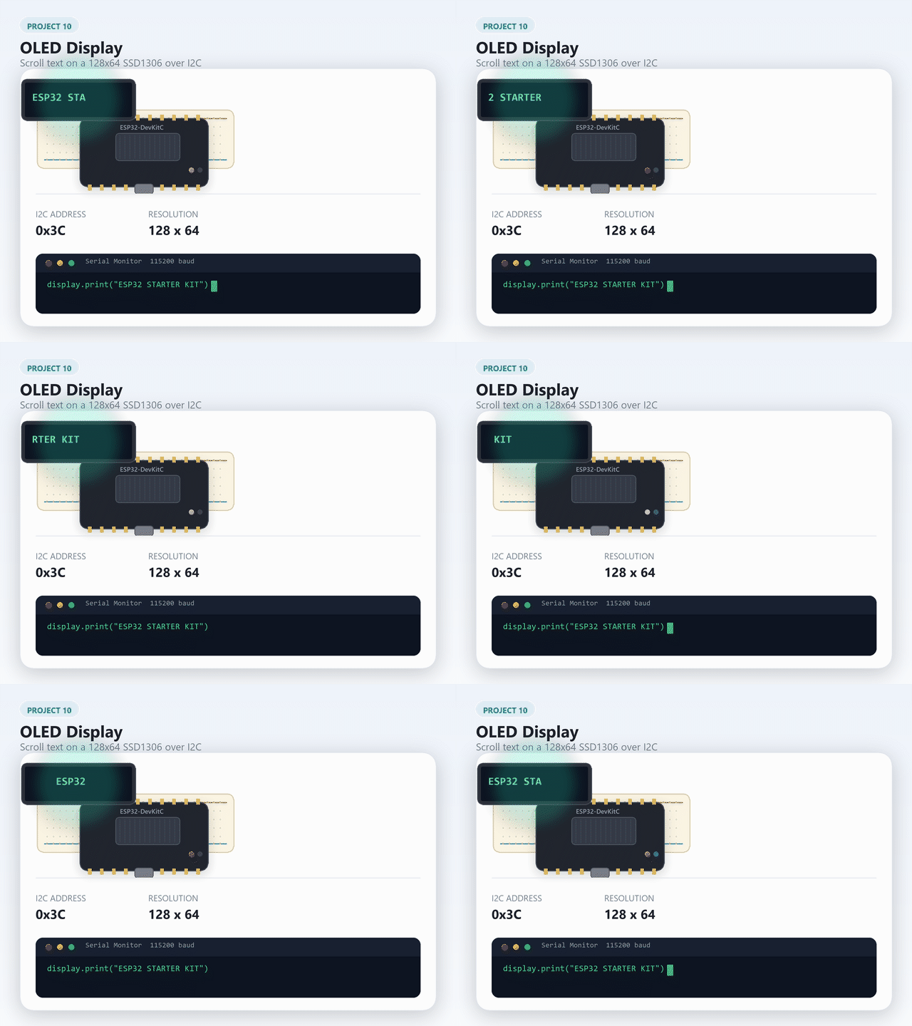
startscrollright() is one command sent once. The SSD1306 then scrolls by itself, in hardware, until told to stop, which is why the delay() calls do no damage here: the animation is not being driven by the ESP32 at all. The two arguments are the first and last page to scroll, a page being an 8-pixel-tall band. 0x00 to 0x0F covers the whole screen.
Key concepts: what each line really does
| Code | What it does |
|---|---|
#include <Wire.h> | The I²C driver: the code that knows how to talk I²C. |
#define SDA_PIN 21 / SCL_PIN 22 | Names the two I²C pins as constants; change these two lines to move the bus. |
Adafruit_SSD1306 display(W, H, &Wire, -1) | Creates the display object: size, which I²C bus, and no reset pin. |
Wire.begin(SDA_PIN, SCL_PIN) | Actually configures the I²C bus on those two pins. Must run before display.begin(). |
display.begin(SSD1306_SWITCHCAPVCC, 0x3C) | Wakes the module at I²C address 0x3C and returns false if nothing answers. |
for(;;); | Deliberate infinite loop. Halts the sketch when there is no display to talk to. |
display.clearDisplay() | Blanks the buffer in RAM, not the screen. |
display.setTextSize(2) | Scales the built-in font. 1 is roughly 6×8 pixels per character. |
display.setCursor(0, 30) | Sets where the next text goes. (0, 0) is the top-left corner. |
display.println("LAFVIN") | Writes into the buffer, exactly like Serial.println() writes to the port. |
display.display() | Sends the whole buffer over I²C. Nothing appears without this. |
startscrollright(0x00, 0x0F) | Tells the display chip to scroll pages 0 to 15 on its own, until stopscroll(). |
Going further: finding devices, drawing shapes, and sharing the bus
Scanning for I²C addresses. Not sure what address a module answers at (or want to confirm this one really is 0x3C)? A short scan sketch will tell you:
#include <Wire.h>

void setup() {
  Serial.begin(115200);
  Wire.begin();
  for (byte addr = 1; addr < 127; addr++) {
    Wire.beginTransmission(addr);
    if (Wire.endTransmission() == 0) {
      Serial.printf("Found device at 0x%02X\n", addr);
    }
  }
}

void loop() {}
Wire.beginTransmission(addr) followed by Wire.endTransmission() is the cheapest possible I²C conversation: "is anyone at this address?" A return value of 0 means something answered.
Shapes and bitmaps. Adafruit_GFX (the layer under println()) draws more than text:
display.drawRect(10, 10, 40, 20, WHITE);             // outline
display.fillCircle(90, 32, 15, WHITE);               // filled circle
display.drawLine(0, 0, 127, 63, WHITE);               // diagonal line
display.drawBitmap(0, 0, myBitmap, 128, 64, WHITE);   // a pre-made image
A bitmap here is a PROGMEM array of bytes you generate ahead of time (an image-to-array converter tool does this from a PNG), one bit per pixel. Shapes and bitmaps land in the same buffer as text, so everything still ends with a single display.display().
Wire clock. The ESP32's I²C runs at 100 kHz (standard mode) by default. Calling Wire.setClock(400000) once in setup(), after Wire.begin() and before display.begin(), switches to 400 kHz (fast mode), which most breakout boards including this OLED support: worth it once you're redrawing the whole screen often and 100 kHz becomes the bottleneck.
Sharing the bus. Because I²C addresses each device, this OLED's four wires can carry a second device too: wire another I²C sensor's SDA/SCL to the same two pins (most breakout boards can be daisy‑chained this way) and give it its own begin() call with its own address. No extra GPIOs needed, which is the whole point of an addressed bus.
Expected output on the Serial Monitor
==============================================
 Project 10: ESP32 OLED Display (SSD1306)
==============================================
I2C: SDA = GPIO 21, SCL = GPIO 22, address 0x3C
[OLED] Display initialized OK.
[OLED] Showing text: "LAFVIN" (will scroll).
The sketch confirms the display started and prints a wiring/address hint if it can't find the screen, instead of freezing silently on failure.
display.display() line at the end of the drawing code, what shows up on screen? Try it (then put the line back).6Demonstration
🎯 Knowledge Check
1. What are the two I2C wires used to communicate with the OLED?
2. What happens if you call drawing functions but forget display.display()?
3. What is the I2C address of the SSD1306 OLED in this kit?
4. How does hardware scrolling work on the SSD1306?
5. What does display.begin(SSD1306_SWITCHCAPVCC) do?
8Wrapping Up: What You've Learned
You now have local output: a device that can report for itself, with no phone, no browser, and no network. The key takeaways:
- I²C carries many devices on two shared wires, so each needs an address. This module answers at
0x3C, and adding a second I²C part costs no extra pins. - A display is driven by layers:
Wiremoves bytes,Adafruit_SSD1306speaks the chip's command set,Adafruit_GFXprovides text and shapes. - Graphics work on a buffer. Drawing edits RAM and
display()pushes the frame, which is why a forgottendisplay()looks identical to broken hardware. - Check that hardware started.
if(!display.begin(...))costs three lines and turns a silent freeze into a message naming the wires to inspect. - Some work belongs to the peripheral, not the CPU. Scrolling runs on the SSD1306 itself after a single command.
- This is a building block. Nothing here is tied to the word "LAFVIN": feed it the DHT11 readings from Project 9, the IP address from Project 5, or the motion state from Project 4.
Now try
- Bar graph: Read an analog input (potentiometer or LDR) and display it as a real-time horizontal bar graph on the OLED.
- Multiple screens: Add a button that switches the OLED between two display modes (e.g., text view and graph view), cycling through them on each press.
9Troubleshooting
| Symptom | Likely cause | Fix |
|---|---|---|
| "display not found" | Wiring or wrong address | SDA→21, SCL→22, VCC→3.3 V, GND→GND; try 0x3D |
| Blank, no serial error | VCC floating | Confirm VCC is 3.3 V |
| Compile error (SSD1306/GFX) | Libraries missing | Install Adafruit SSD1306 and GFX |
| Garbled pixels | Loose I²C wires | Reseat SDA/SCL |