Introduction, Board Tour & Setup
Kit: LAFVIN Basic Starter Kit for ESP32 · Board: ESP32 DEVKIT V1 (ESP‑WROOM‑32, 30‑pin)
The foundation for every other project: what the ESP32 is, how to read its pins, and how to upload your first sketch.
Brand new to electronics? Read Foundation 1: Electronics & Communication Basics first.
🎯 Objective
By the end of this guide, you will:
- Describe what the ESP32 is and what it has on board that an Arduino Uno does not.
- Find your way around the DEVKIT V1: the USB port, the regulator, the EN and BOOT buttons, and the two rows of headers.
- Read the pinout and pick a GPIO with confidence, knowing which are safe, which are input-only, and which will stop the board booting.
- Explain the difference between digital and analog pins, and which pins can do which.
- Install ESP32 support in the Arduino IDE and upload your first sketch.
- Use the BOOT-button trick when an upload refuses to connect.
- Power a breadboard safely from the board, and know the difference between
3V3andVIN.
Still no wiring. This is the tour before the work starts.
1What is the ESP32?
The ESP32 is a low‑cost, low‑power System‑on‑a‑Chip (SoC) from Espressif. A single chip packs:
- A dual‑core 32‑bit processor (Xtensa LX6) up to 240 MHz
- Wi‑Fi (2.4 GHz) and Bluetooth (Classic + BLE)
- 520 KB SRAM and typically 4 MB flash
- ADC, DAC, PWM, I²C, SPI, UART, and capacitive‑touch peripherals
Its built‑in wireless makes it ideal for IoT: several later projects host a web server right on the board.
Deep sleep: the ESP32's low-power mode
Powered over USB, the ESP32 draws tens of milliamps just sitting in loop(). For anything battery‑powered, that adds up fast. Deep sleep shuts down almost everything (Wi‑Fi, most peripherals, most of RAM) and drops current draw to roughly 10 µA: thousands of times less. The chip wakes back up on one of a few wake sources:
- Timer: wake after a fixed duration, e.g.
esp_sleep_enable_timer_wakeup(60 * 1000000)(microseconds), thenesp_deep_sleep_start(). - External pin (
ext0/ext1): wake when a GPIO changes level, e.g. a PIR sensor's output going HIGH. - Touch pin: wake when a capacitive‑touch pin is touched.
A deep sleep wakes the chip like a fresh power‑on (your sketch restarts from setup()), so a real project stores anything it needs to remember (like a counter) in RTC memory, not a normal variable. None of the 14 builds use deep sleep, since it's easiest to learn on hardware you can watch respond instantly, but Project 4's PIR sensor produces exactly the kind of GPIO signal an ext0 wake source is built for, once you're ready to try it on your own.
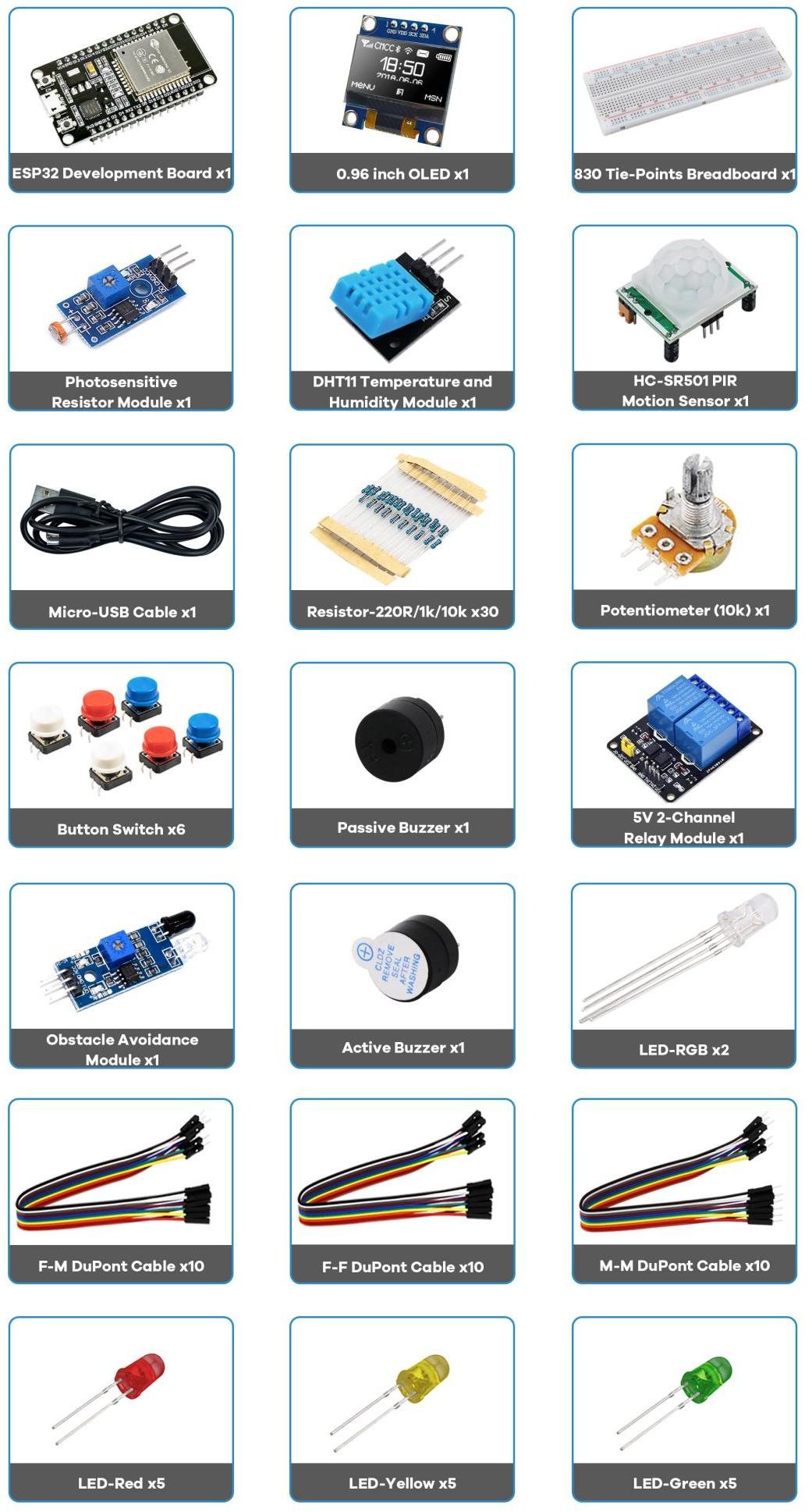
2What's in the kit
3Board tour
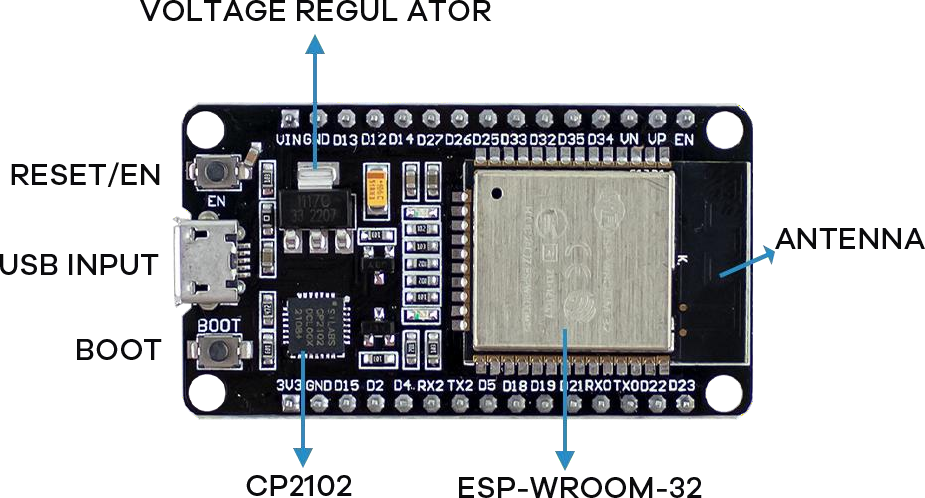
| Part | What it does |
|---|---|
| Micro‑USB port | Uploads code and powers the board. Use a data cable, not charge‑only. |
| CP2102 (USB‑to‑UART) | Bridges USB and the ESP32's serial port. Needs the CP210x driver (§8). Some boards use CH340 instead. |
| Voltage regulator | Drops 5 V (USB/VIN) to the 3.3 V the chip runs on. |
| EN / RESET | Restarts the board and runs the current sketch. |
| BOOT | Puts the chip into flashing mode (§9). |
| ESP‑WROOM‑32 | The metal module holding the chip, flash, and PCB antenna. |
| On‑board LEDs | Red = power; blue = wired to GPIO 2 for debugging. |
4Specifications
| Feature | Value | Feature | Value |
|---|---|---|---|
| Cores | 2 (dual) | SRAM | 520 KB |
| Clock | up to 240 MHz | Flash | 4 MB (typical) |
| Wi‑Fi | 2.4 GHz, 150 Mbps | GPIO header pins | 30 |
| Bluetooth | BLE + Classic | Logic level | 3.3 V |
| USB‑UART | CP2102 | Max current / pin | 40 mA (keep ≤ 12 mA) |
5The pinout
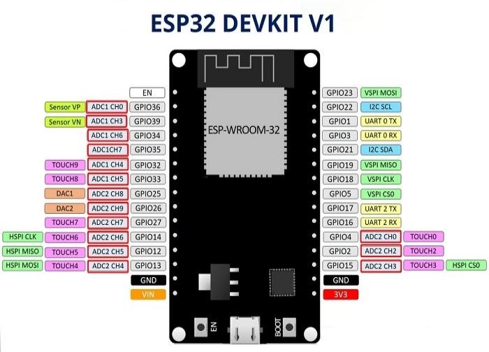
- I²C: SDA = GPIO 21, SCL = GPIO 22
- SPI (VSPI): MOSI 23, MISO 19, CLK 18, CS 5
- UART0 (USB serial): TX0 = GPIO 1, RX0 = GPIO 3
- DAC (true analog out): GPIO 25, GPIO 26
- Power:
3V3(regulated out),VIN(5 V from USB),GND
6Digital vs. analog: the key idea
- DIGITAL: pin is either HIGH (≈3.3 V) or LOW (0 V). LEDs, buttons, relays, buzzers.
digitalRead()/digitalWrite(). - ANALOG IN: measures a range of voltage (0–3.3 V) → a number 0–4095 (12‑bit).
analogRead(). Potentiometer, photoresistor. - ANALOG OUT: two true DAC pins (25, 26); for LEDs/motors we usually fake it with PWM (rapidly pulsing a digital pin).
Two ADC banks:
- ADC1: GPIO 32, 33, 34, 35, 36, 39: always usable.
- ADC2: GPIO 0, 2, 4, 12, 13, 14, 15, 25, 26, 27: cannot be read while Wi‑Fi is on (prefer ADC1 in Wi‑Fi projects).
7Which GPIOs should you use?
| Category | Pins | Notes |
|---|---|---|
| SAFE general‑purpose | 4, 13, 16, 17, 18, 19, 21, 22, 23, 25, 26, 27, 32, 33 | First choice for inputs and outputs. |
| STRAPPING | 0, 2, 5, 12, 15 | Read at boot. Usable, but a wrong level can block uploading: avoid for sensitive inputs. |
| BOOT HIGH/PWM | 1, 3, 5, 14, 15 | Pulse or go HIGH at reset: may glitch attached outputs. |
| INPUT‑ONLY | 34, 35, 36 (VP), 39 (VN) | No output, and no internal pull‑up/down. |
| DO NOT USE | 6, 7, 8, 9, 10, 11 | Wired to the internal SPI flash. |
8Install ESP32 support in Arduino IDE
- Install the Arduino IDE (1.8.x or 2.x).
- File → Preferences → Additional Boards Manager URLs, add:
https://raw.githubusercontent.com/espressif/arduino-esp32/gh-pages/package_esp32_index.json - Tools → Board → Boards Manager…, search esp32, install "esp32 by Espressif Systems": take version 3.0.0 or newer, since Projects 3 and 6 use the Core 3.x PWM functions.
- Tools → Board → select "DOIT ESP32 DEVKIT V1".
- If no port appears, install the CP210x driver (repo folder Install CP2101 drivers Windows).
- Tools → Port → choose the board's port.
9Uploading & the BOOT‑button trick
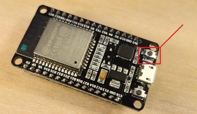
Click Upload, wait for "Done uploading.", then open Serial Monitor at 115200 baud (all our sketches use this).
If you see "Failed to connect to ESP32: … Connecting…":
- Press and hold BOOT.
- Click Upload.
- When "Connecting…" appears, release BOOT.
- After "Done uploading", press EN/RESET to run the sketch.
10Breadboard & power basics
- The outer rails (+ / −, red / blue) run the board's length and carry power. The inner rows connect in groups of 5, split by the center gap.
- Feed logic power from
3V3→ + rail, andGND→ − rail.
VIN, but still drive their signal pins with 3.3 V logic.Reading resistor color bands (this kit ships 5‑band ±1%)
| Resistor | Bands | Used for |
|---|---|---|
| 220 Ω | Red Red Black Black Brown | LED current limiting |
| 10 kΩ | Brown Black Black Red Brown | Pull‑down / pull‑up |
| 1 kΩ | Brown Black Black Brown Brown | General purpose |
Read with the tolerance band (Brown, ±1%) on the right. The first band gives it away: Red starts the 220 Ω; Brown starts the 10 kΩ and 1 kΩ.
🎯 Knowledge Check
1. What is the ESP32's operating voltage for GPIO pins?
2. Which GPIO pins CANNOT be used at all because they are wired to the internal SPI flash?
3. Which ADC bank stops working when Wi-Fi is active?
4. What should you do if no COM port appears in the Arduino IDE?
5. What is the BOOT button used for during upload?
12Wrapping Up: What You've Learned
You now know the board well enough to stop treating it as a black box. The key takeaways:
- The ESP32 is a System-on-a-Chip: processor, Wi-Fi, Bluetooth, and peripherals in one part. The Wi-Fi being on the chip is what makes every project from 5 onward possible.
- The board is not the chip. The DEVKIT V1 adds USB, a 3.3 V regulator, and headers so the chip is easy to program.
- Not every pin is equal. Some are input-only, some are strapping pins that decide how the board boots, and some are wired to internal flash and must never be touched.
3V3powers logic,VINgives you the USB 5 V. GPIOs stay at 3.3 V, always.- Digital pins read two states; ADC pins read a range (0–4095). Only some pins have an ADC, and ADC2 stops working while Wi-Fi is on, which is a trap worth remembering now.
- Uploading has a ritual. The IDE resets the board into its bootloader automatically. When that fails, holding BOOT while it says
Connecting...does it by hand. - 115200 baud, every time. Garbage in the Serial Monitor is nearly always the wrong rate.
Keep the GPIO Reference open in a tab. You will use it in every project that follows.
13Next
Next, set up your software in Foundation 3: Arduino IDE Setup, then build Project 1: Inputs & Outputs (button + LED) and work up through analog input, PWM, sensors, and the Wi‑Fi web‑server projects.
Ask about wiring, code, or troubleshooting for any project in this kit.